Steve
Bedair
Gladewater, Texas
10-2005
Wood Chipper
Pulley's Shafts & Bearing
Holders
Outboard Motor Bearing / Pulley
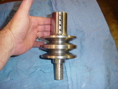
This is a double sheave pulley I turned from a solid piece of 4" round.
The upper part slides onto the shaft of the 14 hp motor and the
bottom of the shaft rides in an outboard bearing support.
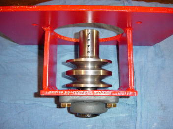
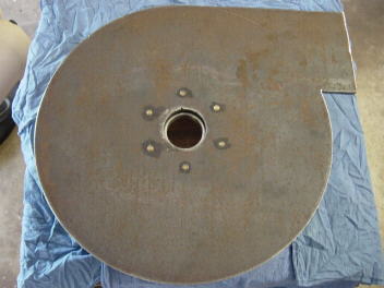
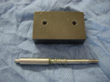
The 14 hp motor bolts to the top of this plate.
The lower bearing is a 1" id 4 bolt flange bearing.
Where the bottom flange bearing bolts to is cut out
large enough so that the double sheave pulley can be
removed from the bottom ( without having to remove the motor)
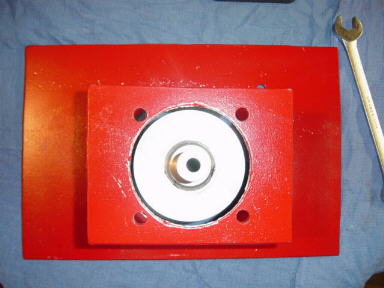
pulley will fit through bottom of idler plate.
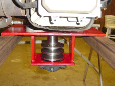
Motor in place
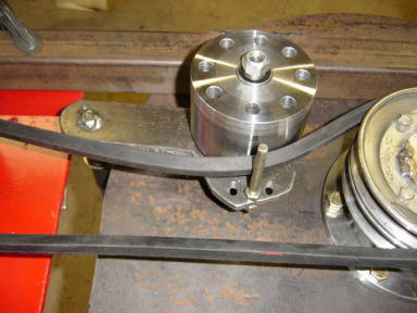
Lower Pulley's
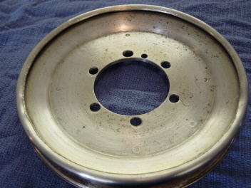
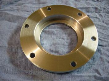
I salvaged these two 6" OD pulleys from the Murry riding mower.
I bored out the ID of the pulley's to fit the adapter shown below.
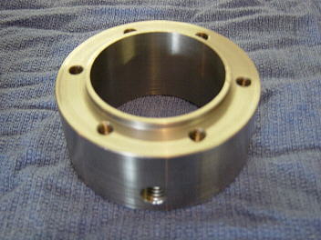
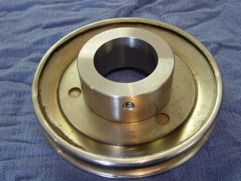
I adapter fits the shaft of the chipper disc.
The pulley is attached to the adapter with 6 grade 8 bolts.
I then attached a second pulley on top of this one to make it a double
pulley
( sorry I don't have a pic, design change)
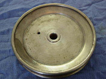
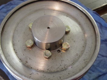
Lower Bearing and Holder
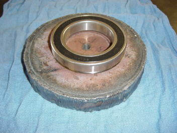
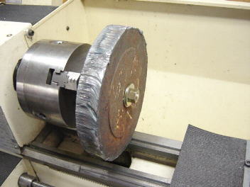
The lower bearing housing started out as a piece of 1 1/4" thick
steel. I used my 9 x20 metal lathe to
build the housing
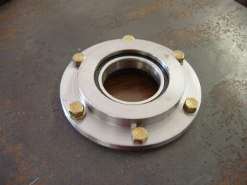
The bearing has a 2 7/8" ID.
This is the lower disc housing with the bearing and holder attached.
Idler Pulley
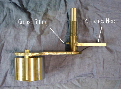
The idler pulley is 3" od.
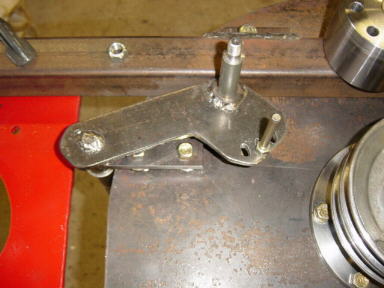
This view is from the bottom. The idler assembly attaches to the
bottom of the disc housing.
The idler is shown with one of the two belts used.
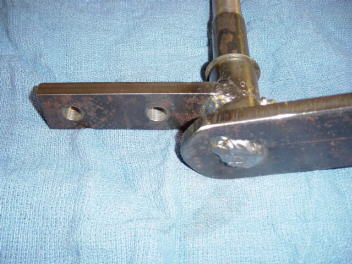
The two small holes are for springs.
A spring loaded pin holds the idler shaft in position
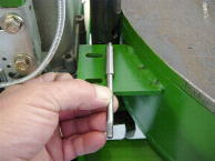
This shows where the pin will fit into a milled slot on the idler shaft
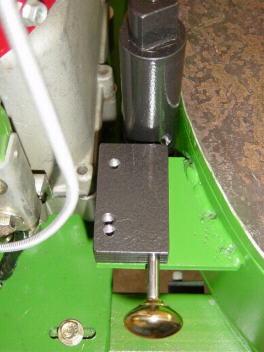
Complete. Pull the pin to release the spring loaded idler assembly.
I later replaced this knob with an aluminum knob I made with
my lathe and ball turning
toolpost.
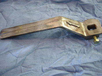
I found the handle at the scrap yard.
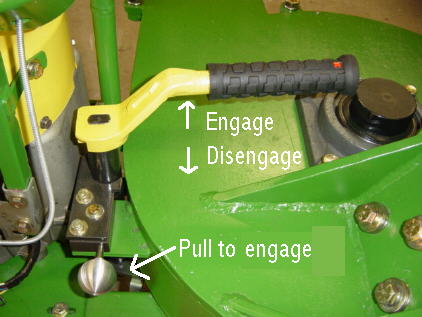
The ball handle is attached to a spring loaded 3/8" pin. When the handle
is pulled
back to the disengage position the the pin locks into a slot on the
idler shaft.
When the ball is pulled back the idler will go to the engage position.
There is also a safety lockout switch that I used from the riding mower
that only allows the chipper to be started when the idler is in the
disengage position.
I've included pictures of the building process.
Just click on the links below.
If you are considering building a wood chipper please read the disclaimer
here
Comments / Questions /
Suggestions or Add Your Link
This information is provided for personal use only.
Copyright 2002 /2005 Steve
Bedair