Bandsaw
Tensioning / Shaft Details
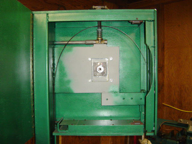
View with the top wheel removed
Another view with the top wheel removed
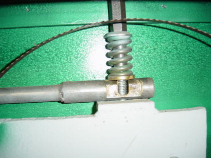
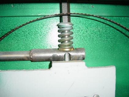
Blade tensioning mech. in the raised position
The 3/8" threaded rod raises the axle plate (not visible here)
The plate pictured here does not move and is welded to the frame.
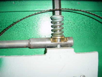
Halfway position
Lowest position ( Blade tension is released )
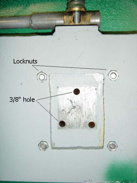
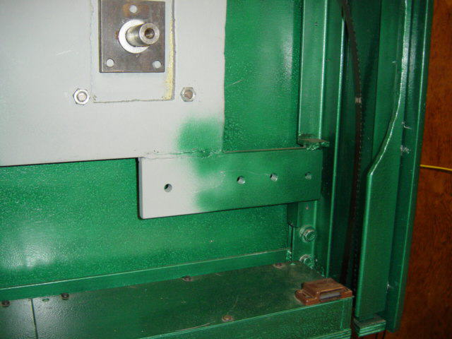
The four outside 3/8" bolts have lock nuts.
The bolts fit loose to allow the axle backing plate to slide up and
down.
There are slots that these bolts ride in seen in the next picture.
The 3 holes for the axle plate are not threaded.
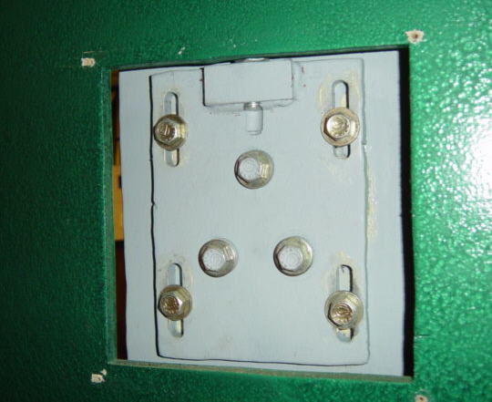
Back view of the axle backing plate.
The 3 bolts in the center are for adjusting roll and yaw.
At the very top of the picture is where the 3/8" threaded rod is attached
to the axle backing plate. This threaded rod is what lowers and raises
the upper wheel.
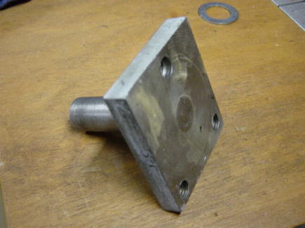
The upper axle is welded to a piece of 2 1/2" x 2 1/2" x 1/2"
thick steel plate.
It's hard to tell but the axle protrudes through the steel plate approx.
1/16" .
The plate has 3 threaded holes that when tightened can adjust the roll
and yaw.
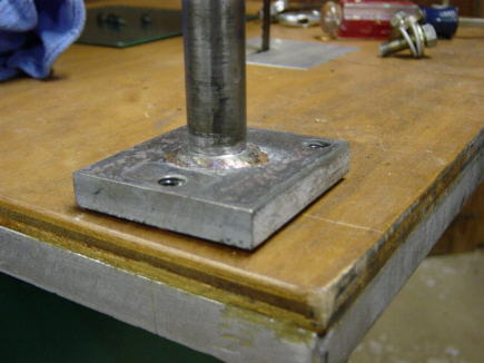
The upper axle. You will notice that it does not sit flat on the table.
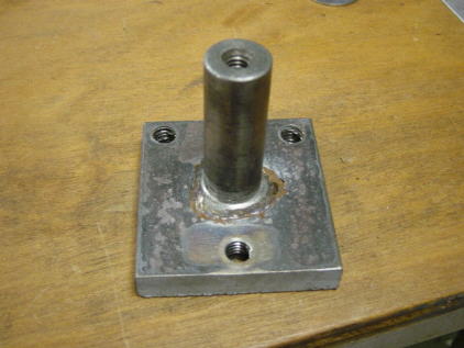
My upper wheel has two sealed roller ball bearings that fit over the
shaft.
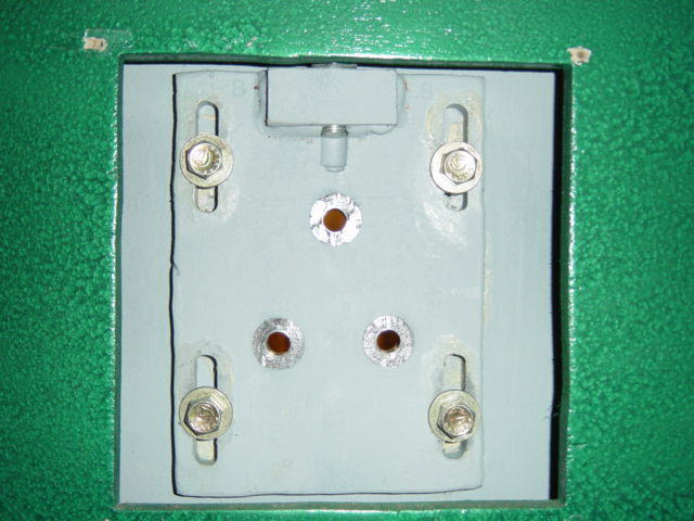
Axle backing plate. Moves up and down to tension the blade.