9 x 20 Spindle Tach
Harbor Freight 9 x 20 Lathe
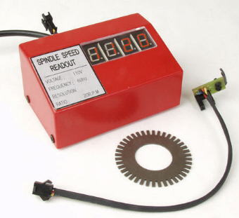
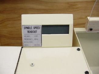
This is a 1684
spindle tachometer sold by Little
Machine Shop. It's sold for the import 7x metal lathes.
The tach reads in increments of 20's ( 0 , 20 , 40 , ect ) and uses
120 vac to power it up.
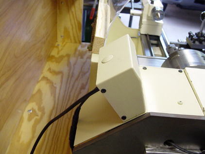
The 27 mm ID encoder wheel attaches to the spindle and the electronic
sensor is placed
to straddle the encoder wheel as shown below. It also includes 4 small
magnets on the base
of the tach to place the tach on the headstock of the 7x machines.
1684 LMS tach on the 9x lathes
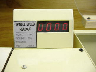
The first thing I noticed when I received the tach was the display.
If you look closely at the picture above
you can see the white outlines of the squares that light up to create
the numbers. These white lines
are visible even when the power is off. When power is applied
the numbers will light up "red"
as shown in the above pic also ( shows 1120 rpm ).
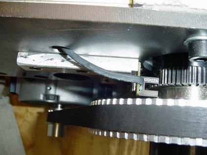
To use the 1684 tach on the 9x lathe also required boring the 27 mm
ID encoder wheel slightly larger to fit the
9x spindle. The electronic pick up will also have to be mounted to
straddle the encoder wheel. The tach
also needs 120 vac for power which can easily be wired through the
existing lathe off / on switch.
And that's it ! Easy to install and works well.
My Modified 1684 Tach
I'm not recommending the modifications shown
below and it will void the warranty.
So travel at your own risk.